For more information about 1063 and the rest of these rare graceful amphibians grab a copy of Steve Ginter's S-43/JRS-1 NF103
Saturday, December 30, 2017
JRS-1 BuNo 1063 ON DISPLAY!
Historic JRS-1 1063 has been reassembled and placed on display at the Steven F Udvar-Hazy Center of the National Air and Space Museum. Here are a few photos of 1063 taken in October:
For more information about 1063 and the rest of these rare graceful amphibians grab a copy of Steve Ginter's S-43/JRS-1 NF103
Sunday, September 24, 2017
V-507 The F-14 That Wasn't Part Three
After the visitors had passed the various information panels the pathway eventually led to the main event, the full size mock up. The mock up was placed in an open, well lit area for viewing and showing off the designs features.
With the V-507, space was given to show the wing sweep design for it's aerodynamic and ship board handling qualities. The mock up also allows a full size representation of height of the aircraft along with the presentation of where the major components are housed in the airframe.
With the AN/AWG-9 Phoenix weapons system being central to the future F-14, the V-507 mock up was able to show the antenna installation along with the ease of access to the avionics boxes used for the system.
All photos courtesy VAHF
Monday, September 4, 2017
V-507 The F-14 That Wasn't Part Two
The V-507 Mock Up is Born
Finally in the photos that were uncovered for this post are the spotting diagrams. As this was an aircraft for the US Navy the ability to move and store the design aboard ship is critical to the success.
As was common practice in the industry since the 1930's, an Operations Specification, Request for Proposal or other documents were submitted to industry and brochures, reports were generated on the company's proposal. The proposals were evaluated and the top one or top two were selected to go further into the development stage with more detailed engineering being accomplished and a mock up built.The V-507 is was selected to continue on to the mock up phase.
The visitor to the V-507 mock up was treated to a series of informational panels along the way to the actual mock up. These panels helped to tell the story of the V-507 and why it was the right choice for the US Navy. Although incomplete, the photos do give signifigant insight into the development of the V-507.
A configuration display was presented with models showing the evolution from the F8U-3 to the V-484, V-505 and eventually the final V-507 configuration.
The threat that needed to be countered was illustrated. This showed that the engineering team understood the challenges facing the new design.
The technical alliance of Vought, Dassault, and Lockheed shown with the contributions of each highlighted.
Vought
- Navy Fighter Design
- Movable Wing Technology
Dassault
- Inlet Design
- TF-30 Operational Experience (Mirage F2, Mirage G)
- Swing Wing Experience
Lockheed
- Air Force Fighter Design
- Titanium Manufacturing Technology
To further illustrate the technical alliance a display of the inlet design was presented along with the metals used in the manufacture of the aircraft along with what components were using titanium.
The display shows different spotting arrangements and compares the V-507 to the F-4 that was the current shipboard fighter. It also shows the V-507 in the hangar with the various other types then on board ship.
That concludes this walk through of the V-507 information boards. As can bee seen in the photos there are other panels and places where the confidential information has been covered over. These were the only photos uncovered thus far of this display, which is amazing that they still exist!
In the next installment of this series the mock up will be revealed.
Sunday, August 13, 2017
V-507 The F-14 That Wasn't
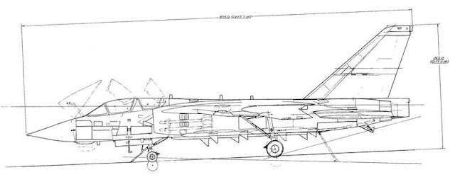
The V-507 was Vought's entry into the VFX competition to replace the unsuccessful F-111B aircraft. Unfortunately, the V-507 lost out to the Grumman 303 design that was designated F-14 Tomcat and went into US Navy and Iranian service.
The design featured swing wings, twin engines with a single vertical tail along with a tandem seating arrangement for the crew. Missile load for the V-507 included the AIM-7 Sparrow, AIM-9 Sidewinder, AIM-54 Phoenix and M61 cannon.
In addition to the AWG-9 fire control system the V-507 also had a provision for a retractable IRST/TV under the nose of the aircraft.
Unfortunately, there was not a fly off and nothing more than a mock up was ever built.
Tuesday, June 20, 2017
Happy 100th Chance Vought Aircraft
June 18, 1917 was the founding day of the Lewis and Vought Corporation in New York City.
June 21st a special celebration was held in Dallas, Texas to commemorate the occasion sponsored by the Vought Heritage Foundation & Retiree Club.
Saturday, April 8, 2017
A2U-1 Major Components
Continuing the information trickle on the A2U-1 attack version of the F7U-3 Cutlass here is drawing CV14-206027 of that shows the major serialized components of the aircraft.
CV10 prefixed drawings and part numbers are F7U-3 components and CV14 prefix drawings and part numbers are exclusively created for the A2U-1.
The part number breakdowns reveal that the A2U-1 incorporated a number of F7U-3 components that were already in production.
It is also interesting that to note the partial interchangeability of the speed brakes, upper left to lower right and upper right to lower left.
Below is a view of the AN7510-2 Plate that was to be applied to each major assembly identified in this drawing.
Other A2U-1 related posts can be found easily by clicking on the A2U button just below this blog's header or by following this link Previous A2U Posts.
Assembly
Designation
|
Assembly
Part Number
|
Name
Of Assembly
|
3
|
CV10-800006-1
|
LH Outer Panel Assembly
|
4
|
CV10-800006-2
|
RH Outer Panel Assembly
|
5
|
CV14-900001-1
|
Center Section Assembly
|
9
|
CV14-600001-1
|
Rear Fuselage Unit Assembly
|
12
|
CV14-150001-1
|
Fin Assembly LH
|
12
|
CV14-150001-2
|
Fin Assembly RH
|
13
|
CV10-140003-1
|
Rudder Assembly
|
13
|
CV10-140020-2
|
Rudder Asembly Aux
|
19
|
CV14-620020-1
|
Tail Cone Assembly
|
20
|
CV14-400001-1
|
Front Section Assembly
|
21
|
CV10-820081-1
|
Wing Tip Assembly LH
|
21
|
CV10-820081-2
|
Wing Tip Assembly RH
|
22
|
CV14-500001-1
|
Mid-Section Assembly
|
24
|
CV10-740036-1
|
LH Slat Assembly Outer Panel
|
24
|
CV10-740036-2
|
RH Slat Assembly Outer Panel
|
25
|
CV10-730035-1
|
LH Slat Assembly Center Section
|
25
|
CV10-730035-2
|
RH Slat Assembly Center Section
|
26
|
CV10-760044-3
|
Speed Brake Assembly (Upper LH
& Lower RH)
|
26
|
CV10-760044-4
|
Speed Brake Assembly (Upper RH
& Lower LH)
|
28
|
CV10-751085-1
|
LH Ailavator Assembly
|
28
|
CV10-751085-2
|
RH Ailavator Assembly
|
CV10 prefixed drawings and part numbers are F7U-3 components and CV14 prefix drawings and part numbers are exclusively created for the A2U-1.
The part number breakdowns reveal that the A2U-1 incorporated a number of F7U-3 components that were already in production.
It is also interesting that to note the partial interchangeability of the speed brakes, upper left to lower right and upper right to lower left.
Below is a view of the AN7510-2 Plate that was to be applied to each major assembly identified in this drawing.
Other A2U-1 related posts can be found easily by clicking on the A2U button just below this blog's header or by following this link Previous A2U Posts.
Thursday, February 23, 2017
TBU Major Components
Here is Vought-Sikorsky drawing VSK-420 showing the Major Components of the TBU-1.
The drawing gives a good visual on how the various components were assembled and brought together to create the finished aircraft. each boxed in area created a unit or section made up of various panels and assemblies.
VAHF Microfilm CVA148 scan
The drawing gives a good visual on how the various components were assembled and brought together to create the finished aircraft. each boxed in area created a unit or section made up of various panels and assemblies.
VSK-3420 Major Components TBU-1 |
Saturday, February 4, 2017
FLIR and LST Aerodynamic Testing on the A-7E
As a further addition to this posting concerning FLIR (Forward Looking Infrared) and LST (Laser Spot Tracker) installation on a YA-7D.
Here is A-7E 156802 in February 1972 with FLIR/LST simulated fairings installed under the air intake. The testing would later lead to pod mounted FLIR and a chin mounted LST on the A-7D/K series only. The A-7D trials would actually start around a year later. For some images of that testing please visit my previous post here: FLIR/IRST Tests on YA-7D 67-14582
LTV-09643U-A-7E-156802-Front-View-FLIR-LST-19720214 |
LTV-09639U-A-7E-156802-RH-Side-View-FLIR-LST-19720214 |
LTV-09640U-A-7E-156802-LH-Side-View-FLIR-LST-19720214 |
LTV-09644U-A-7E-156802-Close-Up-LH-Side-View-FLIR-LST-19720214 |
LTV-09641U-A-7E-156802-Close-Up-Front-View-FLIR-LST-19720214 |
LTV-09642U-A-7E-156802-Close-Up-RH-Side-View-FLIR-LST-19720214 |
Subscribe to:
Posts (Atom)