
Advanced Interceptor
Vought Aeronautics Division heard of interest in hypersonic interceptor aircraft in March 1968. The team went to work on an Advanced Interceptor (AI) study. Driven by Required Operational Capability (ROC) for Advanced Manned Interceptor, (LAO-3119 10 July 1968) from the USAF and a composite cycle engine evaluation study (Request for Proposal No. F33625-69-12-1453, Exhibit “A”. Statement of Work 4 October 1968) the team went to work.
VAD had already proposed a Universal Hypersonic Test Vehicle (UHTV) program earlier in the year. With a further definition of the mission for the AMI the team was able to apply their previous work on the UVHT to the new requirements.
Two of the goals for the project were to formulate aerodynamic design concepts and evaluation of candidate propulsion cycles. Five mission profiles were studies which created 13 different airplane configurations that filtered down to three refined base line configurations.
VAD viewed the mission definition of the AI as tenuous at best. The reason for that view were the different projected requirements of the USAF and SUN in purpose and complexity.
ZAP
The first mission was described as the ZAP. It consisted of the following:
1. Outbound leg of acceleration to Mach 4.5 while climbing to cruise altitude and cruise out to a range of 500 NM.
2. A 3g, power-off decelerating turn to Mach 3.0 at 80,000 ft.
3. Followed by a constant altitude, constant Mach number turn at thrust limited normal load factor not to exceed 3g
4. Engagement segment of 250 NM to inspect and attack the intercepted target.
5. Finally, a cruise and descent to sea level with a twenty minute loiter capability at Mach 0.3.

Armament
The mission profiles assumed six missiles with no specifics on missile type current or projected. For the purposes of the project six missiles totaling 2000lbs and 1000lbs for a 30 mm internal gun and ammunition filled the bill. There was one missile from a McDonnell study called the “Raytheon 400”. The missile featured a compact arrangement which made it a good candidate for internal stowage.
The ZORCH and SNAKE profiles necessitated a larger aircraft due to the range; radar needs and second crew member to operate the radar. Designs included external conformal phased radar antennas but also permitted an interplanar array of 36 in diameter.
Crew Accommodations
There was a requirement for forward visibility equivalent to current fighters, which was a challenge with the heating challenges and high angles of attack for landing which led to tilting nose arrangements. The crew also had to be provided and escape capsule due to the high speeds. A closed-circuit video display was later proposed to eliminate the complexity of the tilting nose.
Engine Types
They engine types evaluated were fascinating in name as well as function: Supercharged Ejector Ramjet (SERJ), Plenum Burning Turbofan, Turbojet, Turboramjet, Rocket Augmented Turboramjet, Airturborocket, Turbofanramjet, Supersonic Inflow Turbofanramjet, Turboramjet-Stoichiometric Core, Afterburning Turbojet and finally Combination, Rocket, Ramjet, Turbofan,
Recommendations
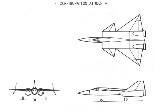
In the end the VAD team developed two base line aircraft designs the A-105 and the A-505. The recommendation also included a design maximum speed of Mach 4.5 due to the constraints of fuel selection and construction materials available at the time. For an engine they stated that the Supercharged Ejector Ramjet (SERJ) and the Turbofanramjet (TFRJ) were the most promising.

AI-105K
Further visuals on the AI-105K


