table

Home VE O2U/O3U SU SBU SB2U OS2U TBU V-173 F4U F5U F6U F7U A2U F8U A-7 C-142 Missiles V Numbers Other Vought
Click on designations above to see relevant posts
Showing posts with label A2U. Show all posts

Saturday, April 8, 2017

A2U-1 Major Components

Continuing the information trickle on the A2U-1 attack version of the F7U-3 Cutlass here is drawing CV14-206027 of that shows the major serialized components of the aircraft. 


Assembly Designation
Assembly Part Number
Name Of Assembly
3
CV10-800006-1
LH Outer Panel Assembly
4
CV10-800006-2
RH Outer Panel Assembly
5
CV14-900001-1
Center Section Assembly
9
CV14-600001-1
Rear Fuselage Unit Assembly
12
CV14-150001-1
Fin Assembly LH
12
CV14-150001-2
Fin Assembly RH
13
CV10-140003-1
Rudder Assembly
13
CV10-140020-2
Rudder Asembly Aux
19
CV14-620020-1
Tail Cone Assembly
20
CV14-400001-1
Front Section Assembly
21
CV10-820081-1
Wing Tip Assembly LH
21
CV10-820081-2
Wing Tip Assembly RH
22
CV14-500001-1
Mid-Section Assembly
24
CV10-740036-1
LH Slat Assembly Outer Panel
24
CV10-740036-2
RH Slat Assembly Outer Panel
25
CV10-730035-1
LH Slat Assembly Center Section
25
CV10-730035-2
RH Slat Assembly Center Section
26
CV10-760044-3
Speed Brake Assembly (Upper LH & Lower RH)
26
CV10-760044-4
Speed Brake Assembly (Upper RH & Lower LH)
28
CV10-751085-1
LH Ailavator Assembly
28
CV10-751085-2
RH Ailavator Assembly

CV10 prefixed drawings and part numbers are F7U-3 components and CV14 prefix drawings and part numbers are exclusively created for the A2U-1. 

The part number breakdowns reveal that the A2U-1 incorporated a number of F7U-3 components that were already in production. 

It is also interesting that to note the partial interchangeability of the speed brakes, upper left to lower right and upper right to lower left.

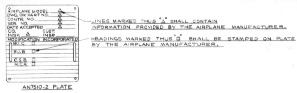
Below is a view of the AN7510-2 Plate that was to be applied to each major assembly identified in this drawing.


Other A2U-1 related posts can be found easily by clicking on the A2U button just below this blog's header or by following this link Previous A2U Posts.

Saturday, July 16, 2016

V-389 More Details

     Continuing with V-389 information is a look at the actual J57-P-4 engine installation into the A2U-1 airframe. This installation drawing shows the placement of the engine and afterburner assembly into the A2U fuselage. 

     Basically aft of fuselage station 265.1 a structural production break the fuselage is new. One major internal change is the changing from a central shear panel (formerly between the two engines) to two shear panels (one on either side of the engine) to absorb fuselage bending loads and fuel inertial loads. 

     All the changes to the fuselage still enable the same wing root rib to be used with the slight exception at the tail cone.


Clip from CVS-37356 V-389 Engine Installation Profile View


Clip from CVS-37356 V-389 Engine Installation Plan View

     Changes to the wing center section was fairly mild. The center-section pylons are moved 9.7 inches aft of the A2U location. The pylons attached to the main wing beam and aft beam instead of the front beam and main beam. 

CVS-37358 V-389 Comparison of V-389 and A2U-1 Plan View

     In addition to the pylons the aft end of the wing root was to be changed to adapt to the new aft fuselage cone for the single exhaust.

CVS-37358 V-389 Comparison of V-389 and A2U-1 Plan View

     Under the skin lighter electrical and hydraulic systems were incorporated. The electrical system would incorporate a separate AC and DC circuits with AC generation taking place by a bleed air turbine generator. Weight would be saved by removing one DC generator, internal battery, and two inverters.

     The hydraulic system incorporated an emergency ram-air-turbine driven hydraulic pump and alternator. The utility system reservoir was redesigned to accommodate the lower fluid volume requirements. One utility system pump was eliminated due to a new higher efficiency pump and the hydraulic oil cooler was eliminated.

     Another subtle change was the installation of only two MK12 guns above the right-hand inlet duct with provisions for a second set over the left-hand inlet duct. 

CVS-37360 V-389 Gun Installation Profile View

The gun muzzles are staggered and located aft of the duct lip instead of in the air duct lip like the A2U-1.

CVS-37360 V-389 Gun Installation Plan View

Source Chance Vought Engineering Report 8847 V-389 Attack Airplane Design Report, NARA II

Thursday, June 23, 2016

V-389 Attack Aircraft

  
     A January 1954 Chance Vought V-389 proposal was for an improved performance attack aircraft based upon the A2U-1 Cutlass. The proposal featured a single Pratt and Whitney J57-P-4 engine replacing the twin Westinghouse J46 engines. A new fuselage section from the inlets aft would be required to house the single engine. The V-389 would share major components of the A2U-1 including wings, vertical tails, landing gear and forward fuselage.


The powerplant change caused a significant increase in radius of action, 280 nautical miles for a total radius of 605 NM while using only internal fuel and carrying two 2,000 lb bombs. 


The V-389 equipped with external fuel and a “special weapon*” had a radius of 815 NM.


AIRPLANE
V-389
A2U-1
ENGINE
J57-P-4
TWO J46-WE-18
Loading
Two 2,000 lb Bombs
3,500 lb Store, 300 Gallon Drop Tank and 220 Gallon Fuel Pack
Two 2,000 lb Bombs
3,500 lb Store, 300 Gallon Drop Tank and 220 Gallon Fuel Pack
Gross Weight
34,830 lbs.
38,170 lbs.
33,950 lbs.
37,330 lbs.
Combat Radius (NM)
605
815
325
500
Max Speed, Sea Level Clean Configuration (kts)
598
598
593
593

There appeared to be little official interest in the proposal and eventually the entire A2U-1 program was canceled. The V-389 is left as another interesting “what if”.


Data from Vought Report 8846 NARA II 

*The F7U-3 was cleared in separation tests to carry the Mk 7, 8, 11, and 12 stores.

The A2U-1 cancellation occurred November 19, 1954

Other A2U related posts: (here) (and here)

Wednesday, March 19, 2014

A2U-1 Cancellation

     The reason for the cancellation of the A2U-1 program was in a November 19, 1954 press release from Chance Vought Aircraft.

In part it read: " Unavailability of suitable engines for an attack version of Chance Vought Aircraft's twin-jet Cutlass fighter has resulted in Navy cancellation of a order for 96 attack airplanes.

          F.O. Detweiler, president of the company, emphasized that the cancellation applies only to the attack version, designated the A2U-1. Other versions of the F7U-3 Cutlass will continue in production.

          The Navy announced in Washington that cancellation of orders for 200 F3H-2 Demon fighers scheduled to be built by McDonnell Aircraft, of St. Louis, Missouri, for the A2U airplanes and for engines, engine spares, radar equipment and other aircraft components for the two aircraft totaled $372,000,000 in a revision of its jet aircraft procurement program.

          The announcement said one of the reasons for the cancellations was delay in development of engines for the airplanes."


                                          CVA-29565 F7U-3M General Arrangement. View
                                          Looking Aft With Two 2,000 LB. Bombs On Center
                                          Section Pylon & Outer Panel Pylon Installed. 11-3-55

Press Release and photo from the VAHF archives

Monday, March 17, 2014

Engineering Project Plan Model A2U-1 Airplanes, Summary of 17 March 1953

A departmental correspondence that detailed the proposed changes to transition the production of the F7U-3 to the A2U-1.

"These were the proposed changes to assure delivery of the first airplane by September 1954.

Basic changes:

1. Addition of Aero 14C launchers, three on each outer panel, and five on the fuselage.

2. Addition of outer panel fuel to provide maximum radius of action and endurance. (This is not really a change, as it was previously agreed with Materials and Manufacturing to provide a common outer panel for the F7U-4 (Sparrow), F7U-3P, and A2U-1 aircraft).

3. Replacement of the right hand forward center-section self-sealing fuel cell with a bladder cell. Addition of internal and external inerting for all center section fuel cells (the same type of inerting will be provided on the interchangeable outer panels).

4. Redesign of main landing gear to replace present 30 x 7.7 wheels and tires with 34 x 9.9 wheels and tires. (In order to assure delivery of the first airplane, a special extra ply 30 x 7.7 tire will be purchased which can be used on the present F7U-3 landing gear. As soon as the redesigned landing gear for 34 x 9.9 tires is available, it will be retroactively installed on all airplanes).

5. Rework of fin stub to accommodate 34 x 9.9 main wheels and tires.

6. Addition of armor protection under the pilot, and under the main fuselage fuel cell pumps.

7. Addition of center section trailing edge area between the vertical tails and the fuselage, to provide increased load carrying capacity and proper balance of the airplane.

8. Removal of the Aero 5A fire control system, including AN/APG-30, and replacement with a simple gun sight.

9. Installation of Mk3 Mod4 bomb-director equipment.

These are the basic changes that will be made to convert the F7U-3 into the A2U-1. There is a possibility (still being investigated) that a change will be required in the machining of the main beams, in order to raise the strength of the airplanes.

The changes outlined above are considered to be the absolute minimum that will assure a satisfactory attack airplane when the A2U reaches the Fleet."

Signed F. Mann

                                          An actual picture of a A2U-1 on the production line.
                                        Memo and photo Vought Aircraft Heritage Foundation