table

Home VE O2U/O3U SU SBU SB2U OS2U TBU V-173 F4U F5U F6U F7U A2U F8U A-7 C-142 Missiles V Numbers Other Vought
Click on designations above to see relevant posts

Friday, December 11, 2015

FLIR/LST Tests on YA-7D 67-14582 In July 1973

VSD-10173U-A-7D-67-14582-Front-View-Mockup-FLIR-LST-19730716
   
     This series of images shows one of the configurations tested on YA-7D 67-14582 during the summer of 1973 for incorporating the FLIR (Forward Looking Infrared) and LST (Laser Spot Tracker) onto the existing Corsair II air-frame.

VSD-10177U-A-7D-67-14582-Right-Side-View-Mockup-FLIR-LST-19730716

     It appears that the chin mounted configuration was associated with the Hughes FLIR system that was canceled which led to the development of the Texas Instruments pod mounted FLIR system. The LST  known as Pave Penny was later incorporated onto the bottom of the engine air inlet of Air Force A-7D/K aircraft.

VSD-10176U-A-7D-67-14582-Left-Front-View-Mockup-FLIR-LST-19730716

     This particular configuration was labeled 4J and the pictures taken prior to flight number 330. Yet to be discovered are the engineering reports that would capture the data and testing results for this and obviously other similar configurations tested on 67-14582. It is also interesting to note that 582 had accumulated 332 flights since its maiden voyage on April 5, 1968
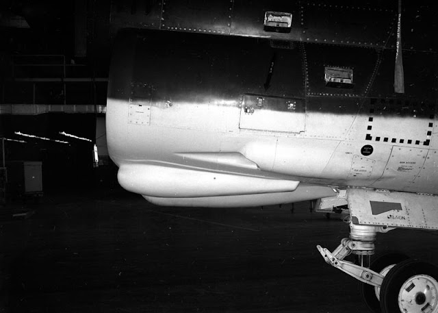
VSD-10175U-A-7D-67-14582-Left-Side-View-Mockup-FLIR-LST-19730716

     All photos from the Vought Aircraft Historical Archives.

Sunday, November 22, 2015

A-7 Mock Up

     There was a request recently for photos of the A-7 mock up other than those already posted of the various weapons fits. I came across these images in the collection previously and had miss-filed them. Here are a few images of the A-7 mock up that was used for inspection and weapons fit testing.

     Ease of maintenance access was an important feature of the V-463 design. Accessing compartments using both a minimum of fasteners and tools along without using a ladder or other external stand was preferred. Lessons long learned from the F7U Cutlass and applied to the F8U Crusader design.

     One of the great maintenance improvements in the A-7 (V-463) was in the area of engine maintenance and repair. The A-7 had a unique design which allowed the engine to be serviced through access panels on the sides and bottom of the fuselage. With the removal of the access panels and tail code the engine could be removed and replaced with out the penalty of having to split the fuselage to remove the tail section as had been done on the F8U Crusader. This eliminated some of the space hogging and special equipment needed for engine changes on board ship.


PR-5435 Left Side View of the A-7 (V-463) Mock Up VAHF Collection


PR-5433 Left Had Rear View Of the V-463 Mock Up. VAHF Collection


PR-5412 Technician Illustrating Access To Cannon, LOX and Avionics Bay. VAHF Collection


PR-5413 Technician Showing Ease Of Access To The V-463's Engine Compartment. VAHF Collection

Sunday, November 1, 2015

F7U-3P Part Three

     Final installment on the F7U-3P Mock Up. These final three images illustrated the access door on the upper fuselage to allow camera installation and film magazine servicing. Along with hold open rods for the door, the hoist for raising and lowering the cameras is installed. It still would have been quite a challenge changing cameras and install in film magazines 12-14 feet off the deck!

CVA-10619-F7U-3P-Door-Stay-Instal-Camera-Access-Door-and-Hoist-19520627
     This next photo shows the Tri-metric mount along with CA-8 and T-6 cameras.

CVA-10445-F7U-3P-TRI-Met-and-Camera-Mount-Showing-All-Configs-19520618
   
     Next up is the mock up of the main instrument board. The main visual difference is the addition of the view finder in place of the gun sight. The viewfinder worked for missions where the aircraft was configured for downward looking cameras for coverage of targets that the photo Cutlass flew over.


CV-10907-F7U-3P-Mock-Up-Main-Instrument-Board-19520729

  The final image shows the oblique sights for camera installations shooting out the sides of the photo Cutlass. A sight was provided on the left and right canopy sills for use depending on the camera configuration mounted in the aircraft.

CVA-10610-F7U-3P-Oblique-Sight-Installation-19520625
     The photos and information for this installment came from Chance Vought Report 7802 Model F7U-3P Mock-Up Photographs dated August 5, 1962. The report was found in NARA 72-AC-30G.

Sunday, October 11, 2015

F7U-3P Part Two

     For those of you who are interested in the details of the reconnaissance portion of the proposal there were a number of images surrounding the camera installations in the F7U-3P.

CVA-10317 F7U-3P General Reconnaissance Configuration 19520613
     The general reconnaissance configuration has a P-2 strike camera in the nose with a K17 camera in Station One along with a K17 or a K38 camera in Station Two with a fixed or rotatable mounts. 

CVA-10318 F7U-3P Mapping and Charting Configuration 19520613
     The charting and mapping configuration removes the P-2 camera from the nose and installs a K17 or CA-8 or T-11 camera in Station One. Station Two is configured with a K17, CA-8 or T-11 Tri-Metrogon assembly.

CVA-10319 F7U-3P Beach and Offshore Reconnaissance Configuration 19520613
     The Beach and Offshore reconnaissance configuration removes the P-2 camera in the nose and adds the CAS-2 rotatable camera in Station Two. The equipment in Station One cannot be properly identified at this time. 

CVA-10320 F7U-3P Night Reconnaissance Configuration 19520613
     The night reconnaissance configuration again leaves the forward bay empty. Station One contains a shutter trip control and Station Two contains a K37 camera.

CVA-10325 F7U-3P Sub Cockpit Showing Camera Viewfinder 19520613
     The photo above shows the viewfinder for the camera installations when the photography is taking place forward or vertically. For visual reference the nose of the aircraft is to the right in the photo.

     That closes out this installment of the F7U-3P mockup. The final installment will feature a few more details and additional information on the design.

Monday, October 5, 2015

F7U-3P Mockup

     Typical with the majority of Naval Aviation fighter designs from WWII to the 1950's a photo reconnaissance version of the F7U-3 Cutlass was proposed and 12 examples eventually built. The type was not issued for squadron service.


xF7U-3P-Concept-with-Cameras-Airbrused-Photo VAHF Archive
     The photo above is a combination of photograph and artist rendering showing a shorter nose than was installed on the actual F7U-3P aircraft. Interesting array of cameras displayed in front of the aircraft as well.

     Contrast the artists composite concept above with an actual F7U-3P (BuNo 129750) on the Vought ramp. The length of the nose and camera window details vary from the concept to the actual.

F7U-3P-129750-Left-Front-View VAHF Archives

     Found in RG72 at the National Archives are the following images of the F7U-3P mockup.
First up is this image of the whole forward fuselage and cockpit section of the mockup.


CVA-10328-F7U-3P-Mockup-19520613

     Below a closeup of the camera window protective covers installed on the F7U-3P mockup.


CVA-10612-F7U-3P-Mockup-Camera-Window-Covers-19520627

     The following image is of the F7U-3P mockup nose section with all the servicing panels open. The panels allow a tremendous level of access to the cameras, optical sight and associated equipment. The first major disadvantage is illustrated in the next image.


CVA-10316-F7U-3P-Mockup-Service-View-19520613

     This photo illustrates the major disadvantage to having a photo version of the F7U-3. The nose high stance of the aircraft makes camera installation and servicing difficult. The height requires the use of a specialized stand to gain access to the cameras and film..


CVA-10618-F7U-3P-Mockup-Camera-Bay-Access-Ladder-19520627
     Mockup photos from the National Archives RG72, College Park, MD

Sunday, September 13, 2015

XF7U-1 122472 September 9, 1948

     Here are some images taken on a mostly cloudy day at the Chance Vought Hartford, CT facility on September 9, 1948, some 67 years ago. The subject is the first XF7U-1 prior to the start of taxi tests. 

     These views show the wings folded with the instrumentation booms that were removed after the first flights due to the vibration caused by them. The wing booms were replaced by a single nose mounted probe. The nose mounted cannons of the F7U-1 are easily visible. Without the full coat of Glossy Sea Blue (ANA 623) paint a number of panel and material details can be seen more clearly. 

CV-31467 XF7U-1 122472 Under tow 19480909 VAHF Collection

     The tall stance of the design is readily visible hand in hand with one of the criticisms that would influence the Crusader and Corsair II is the readily apparent need for stands to access the aircraft. The number, size and complexity of maintenance stands becomes a problem in the crowded spaces of an aircraft carrier.  

CV-31469 XF7U-1 122472 19480909 VAHF Collection
CV-31466 XF7U-1 122472 19480909 VAHF Collection

     While the Cutlass program was moving towards the first flight date it is important to remember that another significant event was taking place in the life of the Chance Vought Aircraft company. During WW II the Government had built a number of modern inland production facilities. Post war a number of these facilities sat idle. The Navy Bureau of Aeronautics approached Chance Vought Aircraft in the fall of 1946 to consider moving to an industrial reserve aircraft plant in Dallas, TX. 

Aerial photo of the former North American Aviation industrial reserve plant in Grand Prairie (Dallas), Texas 1948 VAHF Collection

     During the war North American Aviation had used the facility to build T-6, P-51 and B-24 aircraft. After reviewing the facility and other locations it was decided to ink an agreement with the Navy to move to the  Dallas facility. The announcement was made by the Navy on April 18, 1948 that Chance Vought was going to move to Dallas, Texas. In an internal update to the Dallas move two days prior to the Cutlass photos (in this post) being taken the company reported the following statistics on the move to date:

Total carloads (rail) shipped to Dallas: 164
Total weight of materials shipped: 7,271,972 pounds
Total shipments of household furnishings to Dallas: 132
Total Chance Vought people transferred to Dallas: 204
Total Texans hired: 595

Monday, August 24, 2015

XC-142 Mock-up

     Continuing with the Mock-up theme, here are a few images from the VAHF collection with the XC-142 mock-up as the subject. The mock-up was full size and had a separate section in the hangar for VIP presentations, mock-up board and engineering work.

CVPR-3845-XC-142-Mock-up-Right-Front-Overhead-VAHF-Collection

    This upper view shows the walkways for inspecting and servicing the XC-142 along with the hatches that allow access to the top of the aircraft.

CVPR-3846-XC-142-Mock-up-Left-Rear-Overhead-VAHF Collection

    The XC-142 was a combined project with Vought-Hiller-Ryan. The aircraft was innovative, as well as complicated, for it's time. Linking two engines on the XV-15 and V-22 is a technical challenge, imagine the complexity in linking four turboprop engines and propellers together. And if that was not enough make it a tilt wing for STOL/VTOL operations off of unimproved fields.


CVPR-3856-XC-142-Mock-up-Right-Front-Wing-Vertical-VAHF Collection

     The obvious needs of the four engines are visible in this cockpit image. The center panel is dominated with engine instruments, there are four fire handles on the glare-shield along with the four power levers on the center console. Interestingly the gauges are all turned with the indicator needles pointing to the left rather than having the gauges mounted with the proper orientation to the painted markings of the instrument faces.

CVPR-4010-XC-142-Mock-up-Cockpit-VAHF Collection

     Far more detailed than the OS2U Mock-up of the 1930's, the XC-142 featured retractable landing gear, outfitted cargo compartment and cockpit. Other working features included a tilt-able wing and flaps along with engine mock-ups. Unlike the OS2U there was no radioman-gunner on-board.

     This interior view shows a mix of two different configurations with web troop seats on the left and casualty litters on the right. Just a couple of different missions envisioned for the C-142A.


CVPR-4011-XC-142-Mock-up-Interior-VAHF Collection
    
 The final image in this post shows an Army artillery piece being loaded into the mock-ups cargo compartment. A set of two doors opened to give full access to the cargo compartment. Fold-able ramps completed the accessories needed for smooth loading and unloading of the cargo compartment.


CVPR-4172-XC-142-Mock-up-Artillery-loading-VAHF Collection


Friday, August 21, 2015

August 21, 1956 1,015.428 MPH!

CVPR-820-F8U-1-141345-photo-opportunity-during-a-test-run VAHF Collection

     August 21, 1956 F8U-1 Number 15, 141345, exceeded 1,000 mph over California with Commander "Duke" Windsor at the controls. The speed record was observed and verified by the NAA (National Aeronautic Association). The recorded average speed was 1,015.428 mph which established a new world record for a production military aircraft.


CVPR-866-Checking-Time-After-Run VAHF Collection

     141345 was a standard production F8U-1 with a few small additions. A photo observer along with two barographs were installed in the ammunition compartment and a radar marker beacon was installed in the rocket pack. The aircraft carried it's full compliment of four 20mm cannons for the record runs. The only other alteration was the painting of the underside of the outer wing panels and the vertical fin and rudder florescent flame orange to aid visibility of the aircraft by ground observers.


CVPR-815-F8U-1-141345-Mojave-VAHF-Colllection

CVPR-828-F8U-1-141345-being-towed-from-hangar-at-Mojave VAHF Collection

     The Thompson Trophy was awarded to CDR Windsor at the 1956 National Airshow at Will Rogers Airport, Oklahoma City over Labor Day weekend.

CDR-Windsor-Thompson-Trophy-September-1956 VAHF Collection

     Here are links to two videos are excellent resources for those looking for more information on the record setting flight.

News reel ; F8U Record Flight

Vought reel: Project_One_Grand

Saturday, August 15, 2015

A-7A Mock Up Weapons Loading 1964 Part Five and Final!

     For this fifth and final installment illustrating some of the various loads tested on the A-7A Mock up go from the mundane (slicks and snakes) to the ALDS. Enjoy!

Here are MK-81 slicks and Snakeyes along with MK-82 Snakeyes sharing the wing of the mock up.

LTV-65500U-A-7A-Mockup-MK-82-MK82-Snakeye-MK-81-Snakeye-19640623 (VAHF Collection)

     Next up the deadly combination of the AGM-45 Shrike and the MK-57 (Later designated B57) and MK-43 (Later designated B43) nuclear bombs.

CVC-65412U-A-7A-Mock-up-Shrike-MK-57-MK-43-19640612 (VAHF Collection)
     This load is a MK-20 Smoke Tank and MK-116 Weteye chemical bombs.

LTV-65530U-A-7A-Mock-up-MK-12-Smoke-Tank-and-Weteyes-19640625 (VAHF Collection)
     Finally, the series will end with a bit of a mystery. This store is listed as the AERO-18A ALSD. Searching the ole interwebs for AERO-18A ALSD brings up Aero L-39, lots of drug references (LSD) but nothing that looks like a combination ECM pod and external fuel tank, If anyone out there can add something, please do!

CVC-65421U-A-7A-Mock-up-AERO-18A-ALSD-19640616 (VAHF Collection)
     That concludes this five part series on external loads hung on the A-7A full scale mock up, Maybe there was something new or of interest to you.


Friday, August 14, 2015

A-7A Mock Up Weapons Loading 1964 Part Four

     As this series on the A-7A Mock up weapons loading continues the focus shifts to how to load all that hardware on the jet. These images show the mock up of the integral pylon hoist mock up and the bomb farm that supported all the different configurations that were loaded on the A-7A mock up.

LTV-66501U A-7A Mock up Integral Pylon Hoist Mock Up Utilizing a Mechanics
Speed Handle Socket Wrench 19641201 (VAHF Archives)
LTV-66503U A-7A Integral Pylon Hoist Mock-up Utilizing Milwaukee half-inch drill and 10 volt EverReady
Nickel-Cadmium Belt 19641201 (VAHF Collection)
LTC-66502U A-7A Mock up Integral Pylon Hoist Utilizing 12 volt battery powered Half-inch
electric drill by Milwaukee Electric 19541201 (VAHF Collection)

     Look at that cordless drill and battery pack, and you thought your's was heavy!.

LTV-66505U A-7A Integral pylon Hoist Mock up Milwaukee and Black and Decker Half-inch
Drills with Batteries and Chargers 19641201 (VAHF Collection)
     Here is one view of the stores array to support the A-7A mock up trials. Rocket pods, drop tanks, Snakeyes, and refueling stores are visible in this image.

LTV-65537U A-7A Mock up Stores Array 19640625 (VAHF Collection)
     In this second view of the stores array mines, cluster bombs, tactical nuclear weapons shapes, and Walleyes are visible.

LTV-65538U A-7A Mock up Stores Array 19640625 (VAHF Collection)

Sunday, August 9, 2015

A-7A Mock Up Weapons Loading 1964 Part Three

    The Navy A-7 aircraft was a well known, long serving "Buddy Tanker". This ability was illustrated in the mock up fitting trials at Grand Prairie. Here are a few photos of the Beechcraft Model 385 refueling store and the D-704 refueling store. VAHF photos.

CVC-65425U-A-7A-Mock-up-Model-385-Refueling-Store-19640616


CVC-65426U-A-7A-Mock-up-Model-385-Refueling-Store-19640616

LTV-65408U-A-7A-Mock-up-D-704-Refueling-Store-19640612


LTV-65409U-A-7A-Mock-up-D-704-Refueling-Store-19640612


LTV-65534U-A-7A-Mock-up-D-704-Refueling-Store-19640625


LTV-65535U-A-7A-Mock-up-D-704-Refueling-Store-19640625


LTV-65536U-A-7A-Mock-up-D-704-Refueling-Store-19640625